Sliding Rheostat, 0-10 Ohms - 2A
$11.29
Description
This Sliding Rheostat has nickel and copper alloy resistance wire and employs an oxide film insulating layer applied to the porcelain tube.
Concept
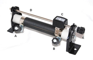
A rheostat offers a resistance that can be altered in a continuous manner. Our sliding rheostat features a coil of bare nickel and copper alloy wire wound uniformly around a porcelain cylinder. Click on the product photo above to enlarge the labels. Alternately you can view the product instructions by clicking on the yellow link above right. The ends of the coil are connected to two binding screw terminals, A and B. C is a metal contact which moves along a rod D, which also contains a binding screw terminal at E. If the screw terminals A and B are connected to a circuit, the whole of the circuit resistance is included in the circuit and the metal contact C becomes ineffective. But if the terminals A and E are connected to the circuit, the actual resistance included in the circuit is determined by the portion of the coil between A and C, and so can be varied by altering the position of the contact C. Thus, by sliding the contact C, the resistance between the terminal A and E (and also between the terminal B and E) can be changed almost continuously.
Specifications
0-10 Ohms
2A


